
Detailing Shelf Angles
This FREE AIA masonry education course will help you:

1) Understand the specific purpose and definition of a shelf angle, and how to use them properly for various building applications.
2) Learn the various ways a shelf angle can be adjusted, and how different adjustments can serve a variety of purposes that compensate for construction tolerances.
3) Understand the problems that may arise from horizontal breaks in the wall cavity caused by shelf angles, and how to properly adapt shelf angle and flashing installation to meet these challenges.
4) Learn the different shelf angle installation methods for both steel and concrete structural frames, and how a shelf angle should be adjusted in accordance with these different frames.
MAC's masonry education is provided by
Walter A. Laska, President - Masonry Technologies
This nano learning course has been approved for .5 AIA accreditation. Read this article and answer the 5 questions below to receive credit.

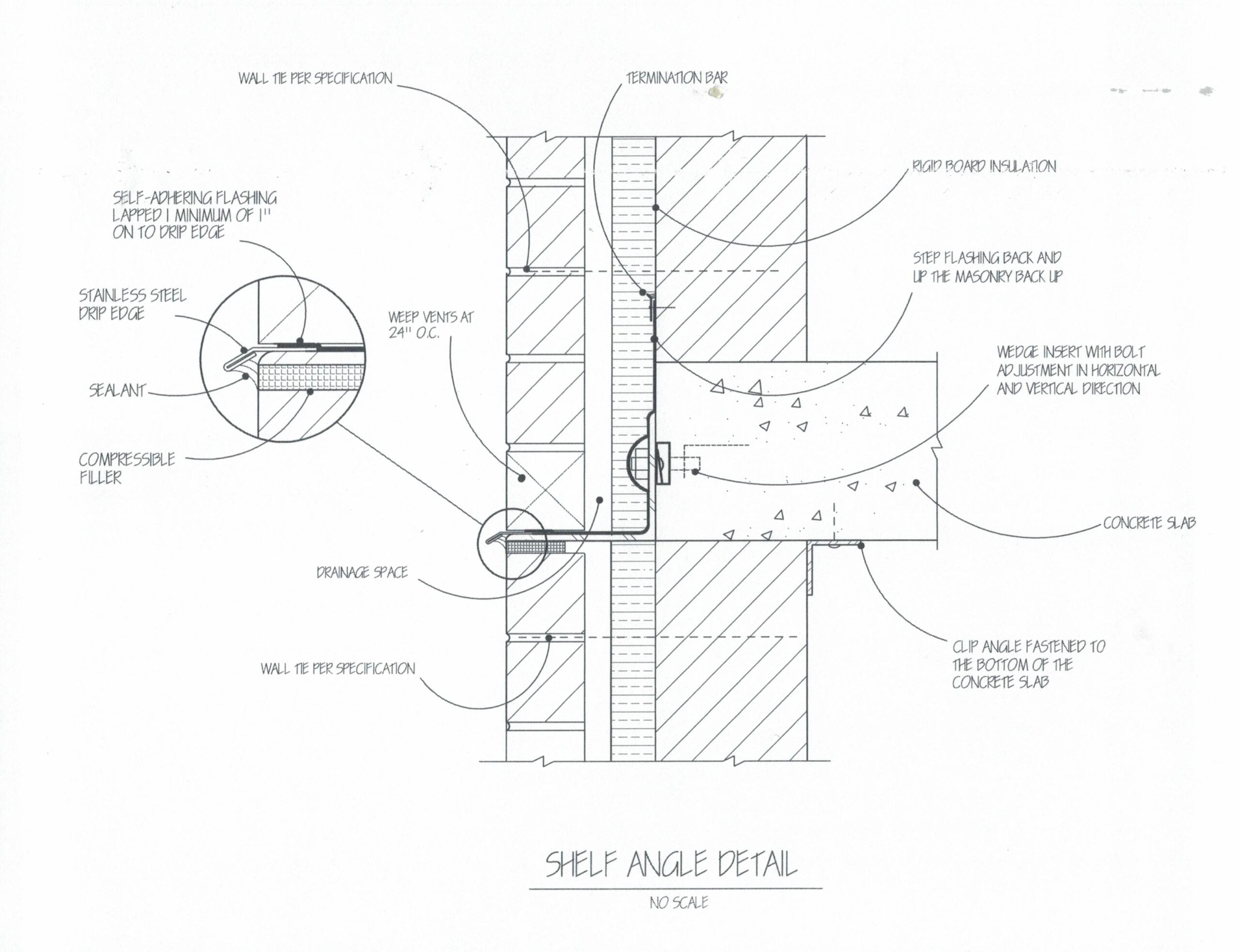
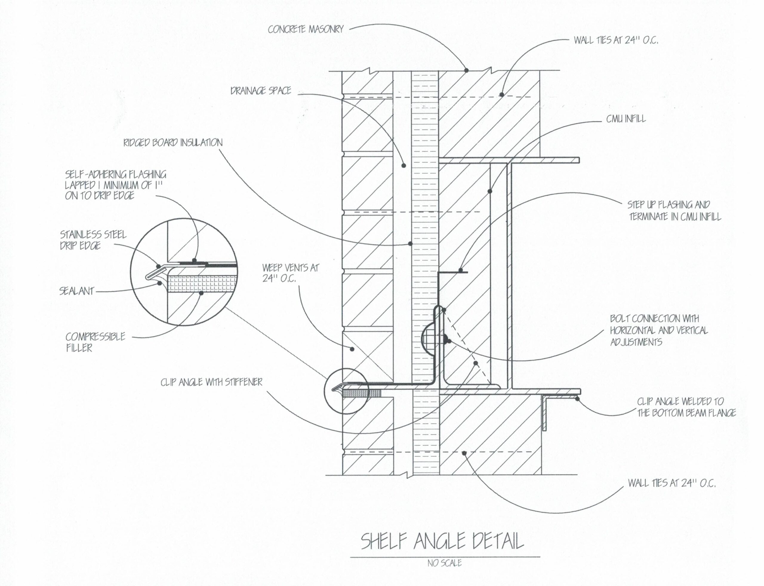
Figure 1 Figure 2 Figure 3
Figure 2 and Figure 3 illustrate shelf angle details for concrete frame and steel frame design.
To see details, click on the drawings to englarge the image.
Detailing Shelf Angles
A shelf angle is a structural steel member that supports and transfers the dead load of the outer brick wythe back to the building frame. Commonly detailed on masonry-clad buildings, these horizontal steel angles are attached to the frame at vertical intervals.
Shelf angles can be connected to the building’s structural frame in several ways.
If the structural frame is concrete, the angle is bolted to inserts cast in the concrete spandrel or floor slab. The vertical leg of the shelf angle is supported by the concrete slab.
If the structural frame is steel, clip angles are required to support the shelf angle. Concrete masonry can be installed within the outer portion of the shelf angle, between the beam flanges.
The installation of the concrete masonry between the two beam flanges creates a plane on which to terminate the flashing. It also can help to stiffen the angle. However, the CMU will require cutting due to the clip angle stiffener. Cutting might be reduced by spacing the angle with a stiffener at 16” intervals to accommodate the length of the concrete masonry units.
The interior concrete masonry can be laterally supported by installing a clip angle against the concrete masonry and securing the angle to the steel or concrete above.
Shelf Angle and Masonry Movements
A shelf angle can rotate outward, creating high, concentrated stresses in the masonry. To prevent this, the shelf angle should be supported as needed with plastic or stainless steel shims spanning the full height of the angles vertical leg.
It is important that sections of shelf angle be placed between 1/16” to 1/8” apart. This will prevent the sections of shelf angle from butting and possibly buckling at some locations due to thermal and frame movement.
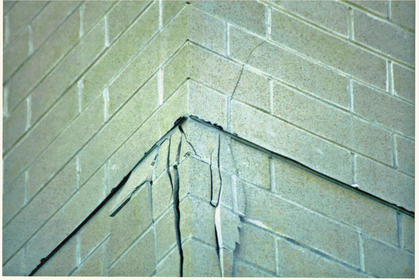
Also, shelf angles must be installed continuously around all major corners of the building. If shelf angle continuity is not maintained at corners, the brick could be unsupported at the corner, causing the brick to crack due to differential movement at each wall corner (photo #1).
Thermal Expansion of the Brick
In addition to other masonry and frame movement, the exterior wythe of brick will expand vertically. The outer brick wythe can expand vertically in excess of ½ inch, depending upon the height of the building and the amount of shelf angles.
Additional movement will occur due to CMU shrinkage and concrete frame deformation. This movement must be accommodated for. Otherwise, the brick might crack.
To accommodate masonry and frame movement, a continuous horizontal expansion joint must be designed and constructed directly below every shelf angle. The joints must be totally void of mortar or any other obstruction. The joints should then be filled with a highly compressible material or the joints should be left open and cleaned. The joints should then be filled with a permanently elastic sealant.
Shelf Angle Adjustability
A shelf angle must have adjustability to accommodate allowable construction tolerances and to assure the angle is level and aligns with the outer brick wythe. The angle should be adjustable in three directions.
For concrete construction, a wedge insert with vertical slots can be set at the outer face of the concrete spandrel or slab: The wedge insert will provide vertical adjustability, horizontal slots in the shelf angle will provide horizontal adjustability, and shims will provide outward adjustments.
For steel construction, an adjustable bolted or welded steel clip angle should be used to connect the shelf angles to the steel beam. This connection is more complex and more difficult to install than a shelf angle-to-concrete beam connection. (figure 1)
The steel clip angle connection will allow the workman to make the required adjustment. The slotted clip angle and slotted shelf angle are loosely bolted to the beam during initial construction. The proper adjustments of the angle then are made by the mason. Once the shelf angle is in place, the angle can be tightly bolted.
Flashing
A shelf angle creates a horizontal break in the drainage wall cavity. Subsequently, a plain is created where water can collect. Therefore, the flashing must be designed and installed carefully at this location.
The outer horizontal leg of the flashing should extend beyond the face of the wall with an extended stainless steel drip. Also, a termination along the top of the inner-vertical leg of the flashing will prevent water intrusion into the wall.
Drip edges perform three functions. They assure that water collected on the inner flashing is drained out to the exterior of the wall. They divert rainwater that is sheeting down the wall away from the building and they create a projection along the shelf angle to apply continuous sealant under.
The vertical leg of the flashing can then be installed in two manners. A termination bar can be set in mastic and installed over the top of the vertical leg of the flashing or the flashing can be terminated within the concrete masonry backup.
Wall Ties
A non-adjustable wall tie or horizontal joint reinforcement is required by the TMS Masonry Code to be installed within the masonry wall at a maximum of 24” o.c. vertically and 36” o.c. horizontally. If the wall tie is non-adjustable, the wall tie must be placed every 16” o.c. vertically and horizontally. The design of the shelf angle should take this into consideration.
Shelf Angle Vertical Spacing
Detailing and installing shelf angles requires proper care. Problems may occur if shelf angles are improperly designed or constructed. Consequently, the fewer shelf angles required on a building, the fewer problems are likely to occur.
In some cases, one shelf angle can be installed every three stories (depending upon local code). This requires an increased expansion joint thickness and structural analysis by an engineer.
In other cases, shelf angles can be eliminated entirely. Brick veneer, more than 90 feet high, can bear directly on the foundation. Mid-rise buildings with exterior masonry bearing walls can commonly be designed and constructed in this manner.
Answer these 5 questions correctly to receive your education credit:
Thank you! Your answers will be reviewed and an email will be sent to you confirming accreditation.